
What a work print is
A fiber optic work print (a splice print, cut sheet, or splicing detail) is the drawing that tells you how to build one or more splice points. Everything on it serves one question: for each cable at the closure, which fibers land where. An engineer draws it, a splicing contractor works it, and the operator owns the plant it describes.
The sheets vary by vendor, but they're all built from the same five parts: a title block, the cables, their count stacks, the connections between them, and a legend. Learn those once and a print from any operator reads the same way.
Start with the title block
The title block is the framed strip of fields, usually down one edge or across the bottom corner. It doesn't tell you how to splice anything; it tells you whose plant this is and which sheet you're holding, which matters the moment you have more than one print in the truck.
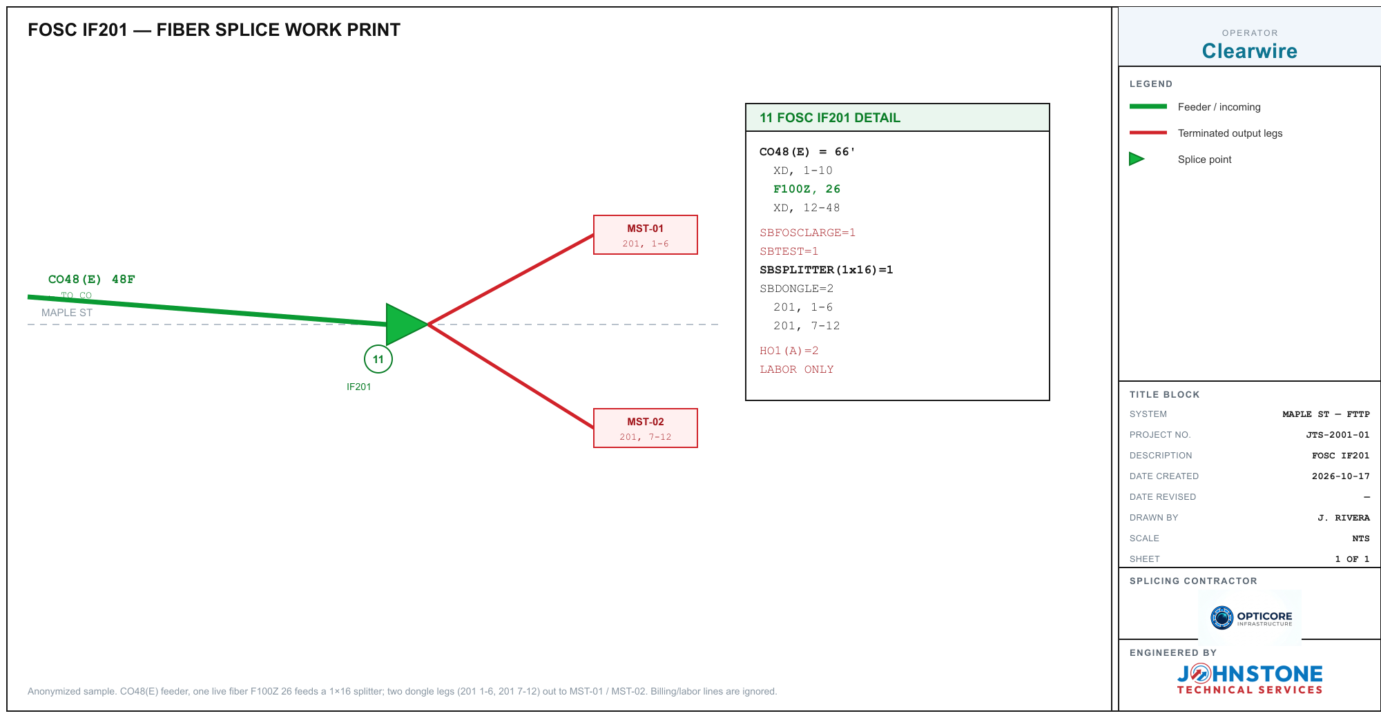
The fields you'll see most:
- Operator (or Company) is the carrier whose network this is.
- System and Project number tie the sheet to a job and an area.
- Description names the splice or the route the sheet covers.
- Drawn by, date created, and date revised track who made it and when. A later revised date means someone changed the design, so check the revision notes before you trust an older markup.
- Sheet (1 of N) tells you how many pages the job runs to, so you know when a cable leaves this page for another one.
- Engineered by and splicing contractor name the firm that drew it and the crew working it.
The cables and their counts
Each cable is a box or a labeled line with its fiber count, like CO48(E) 48F or FDH-144 144F. Inside or beside it is the count stack: the list of circuit ranges the cable carries, one line each.
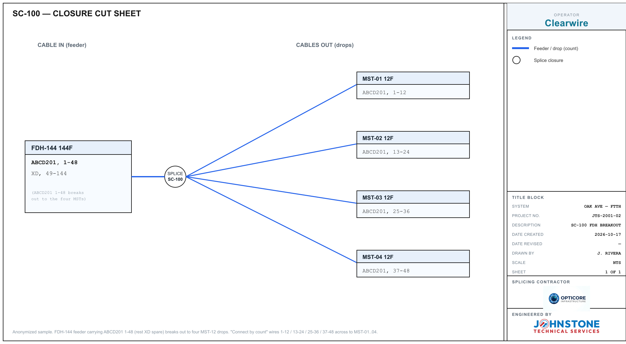
A count is a named circuit set with a range, like ABCD201, 1-48. The name is the fiber's identity for its whole life across the network, so at any splice you match the same name and number on both sides. The ranges in a stack partition the cable's fibers and always add up to the count. A 144ct that reads ABCD201, 1-48 then XD, 49-144 is 48 working fibers and 96 spares. When the math doesn't add up, you've misread a line, and that's the cheapest mistake to catch before the splicer is hot.
Reading the colors
Many prints color-code the route so input and output read at a glance. A common convention: the feeder or incoming cable is green, and terminated output legs are red. On the sample above, the green line is the CO feeder coming in and the red legs run out to the terminals. The legend on the sheet always spells out what each color means, so start there rather than assuming, because conventions differ between operators.
Splice symbols and splitters
The splice itself is usually a simple mark where cables meet: a small triangle, a circle, or a filled node. On a triangle, the flat base is the side the input comes in and the apex points to the outputs. A number by it is the splice or closure ID.
FTTH prints often show a passive splitter in the splice, written as SBSPLITTER(1x16) or similar. One fiber feeds its input and the split legs run out to terminals. Those are real parts of the build and belong in your count.
What does not belong in your count are the billing and labor lines: entries like SBTEST=1, SBFOSCLARGE=1, HO1(A)=2, or LABOR ONLY. They tell the contractor what to invoice, not what to splice. Read past them when you're tracing fibers.
Two layouts: cut sheet and route map
Most prints are one of two shapes. A closure cut sheet is a single splice drawn in detail: the cable in, the cables out, and each one's stack. The feeder-to-MST breakout below is a classic cut sheet, where one 144ct FDH feeder fans out to four 12-fiber drops.
The second shape is a route or construction map: the cable drawn along a street, with numbered call-out boxes holding each splice point's detail spread across the sheet. You read it by following the main line and checking the box at each node. The backbone overview below runs a 1728ct route through seven splice points, with a cross-connect branch peeling off to a second route.
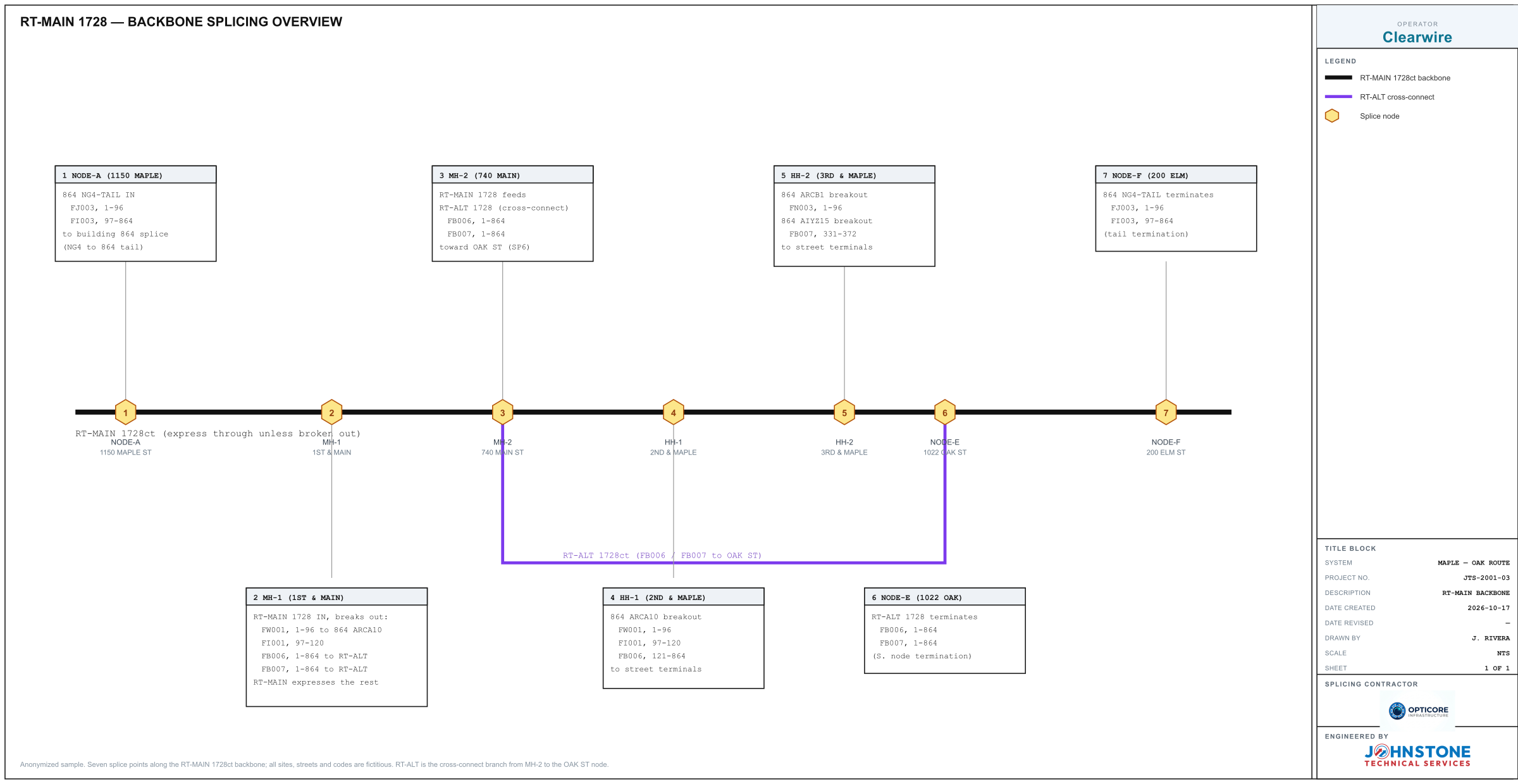
On a route map a count that isn't worked at a node simply expresses through it, carrying on to the next closure untouched. The call-out box only lists what breaks out there, so anything not mentioned keeps going.
Dead and spare fibers
Fibers that aren't used at a splice are marked, not hidden. You'll see XD, dead, or a plain spare range, and the number is the physical fiber (XD, 49-144 is fibers 49 through 144 sitting idle). They matter because they still occupy positions in the cable, so counting them keeps your stack math honest.
Read one yourself
The fastest way to get fluent is to run a print through a tool that draws the splice back to you. Open the free Splice Matrix Builder, hit Scan, and drop in a photo or PDF. It reads each cable's stack, keeps the billing lines out, wires any splitter from the feeder, and connects the counts that match across the splice. Grab one of the sample prints from this guide to try it on:
Turn a print into a working matrix. Scan a work print and the builder draws the splice, counts and all, free and in your browser.
Open the Splice Matrix Builder →