
What a splice matrix is
A splice matrix is the diagram of a single splice point. One side is the cables entering the closure, the other side is the cables leaving it, and the lines between them are the fibers spliced across. It answers the one question you have with a fusion splicer in your hand: this fiber connects to that one.
A work print is the source document an engineer hands you. A splice matrix is the clean, fiber-by-fiber version of one closure on that print. The print tells you the plan; the matrix is the plan laid out so you can work it.
Reading the two sides
Cables in sit on one side, cables out on the other. Each cable shows its label and fiber count, with its count stack underneath: the named circuit ranges it carries, one line each, like ABCD201, 1-48 then XD, 49-144. The feeder-to-MST splice below is about as plain as it gets: one 144ct feeder in, four 12-fiber drops out.
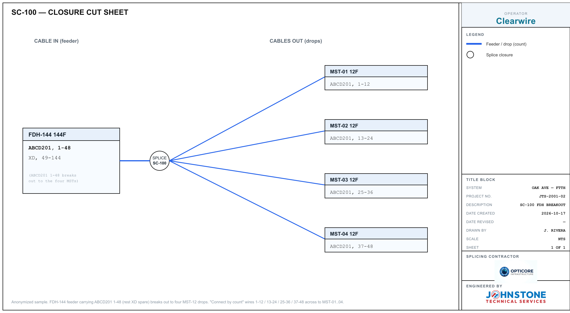
To check a splice, you read across. The feeder carries ABCD201, 1-48. MST-01 takes ABCD201, 1-12, MST-02 takes 13-24, and so on. Same name, consecutive ranges, and the four drops add back up to the 48 working fibers. If a range on the right has no home on the left, or the totals don't balance, the matrix is showing you a problem before it becomes a splicing error.
The connection lines
Every line is a fiber (or a range of fibers) spliced through. A count that stays whole draws as one clean hand-off. A count that splits across several output cables, like the feeder above, fans into one line per drop. The point of the matrix is that you never have to hold the mapping in your head: if a line is drawn, that splice is planned, and if it isn't, it isn't.
Connect by count is how the matrix gets built without hand-wiring every fiber. It matches counts by name and number across the splice and draws the lines for you, then reports anything that didn't find a match on both sides. That report is the useful part: it's the list of fibers that don't splice through here, which is exactly what you want flagged.
Collapsed tubes vs expanded fibers
A 1728-count closure drawn one fiber at a time is unreadable. So a matrix lets you collapse a cable down to its buffer tubes or ribbon groups to see the whole splice at a glance, then expand just the one group you're working to see individual fibers. A collapsed cable still shows its full stack, like a count sheet, so you don't lose the detail; you just fold it away until you need it. The habit on a big closure is to keep everything collapsed, expand the group in front of you, splice it, collapse it again.
Splitters in the matrix
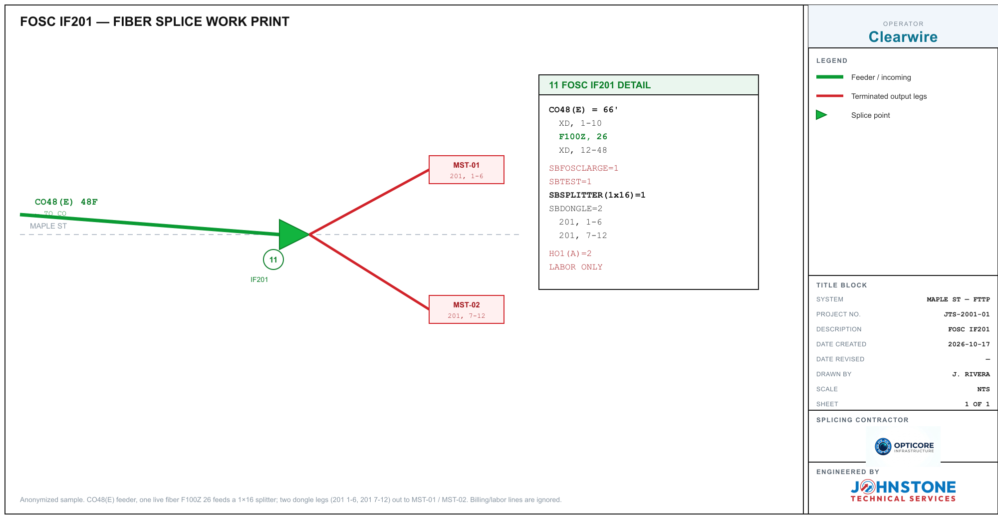
FTTH closures often have a passive splitter. In a matrix it behaves like any other cable: one input, fed from a live fiber on the feeder, and N outputs numbered 1 to N, each running out to the leg it serves. The input lands on a real fiber, not a circuit number, so a splitter fed by circuit F100Z, 26 connects to whatever physical fiber that circuit sits on.
Dead fibers and carry-through
Not every fiber splices here. Spare and dead fibers carry an XD or dead label and are left out of the through-splice, with their number marking the physical fiber. Anything you don't assign a count to is filled with XD so every fiber is accounted for.
A fiber that doesn't land at this closure but carries on to the next one draws as a carry-through stub: a labeled line leaving the edge of the sheet, the way an express fiber shows on a cut sheet. It tells you this strand passes through untouched and picks up at another splice, so you don't go looking for a connection that isn't supposed to be here.
The as-built
When the splice is done, the matrix is your as-built. Printed, it comes out like an engineering sheet: a title block naming the operator, the job, and who built it, with the splice drawn exactly as it was worked. That's the record that goes back with the job, and the thing the next tech reads when they open the closure a year later.
Build or check one yourself
The quickest way to read matrices fluently is to make one. Open the free Splice Matrix Builder, add your cables in and out, type each stack one line per count, and hit Connect by count. Or skip the typing: hit Scan and drop in a photo or PDF of the print. Try it on a sample:
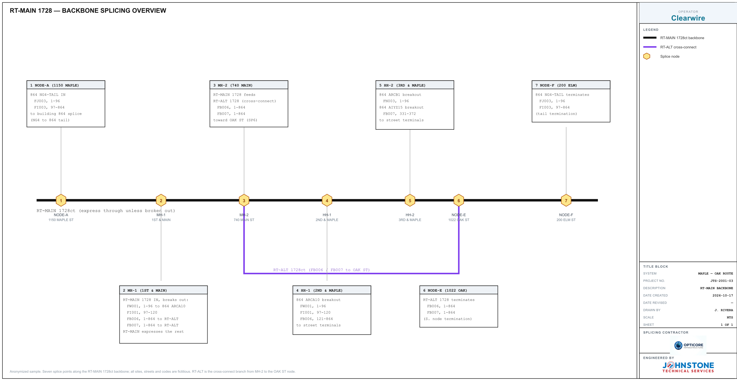
Draw your splice, counts and all. Build it by hand or scan a work print, then print or export the as-built, free and in your browser.
Open the Splice Matrix Builder →